
Creo 8.0 includes a raft of new improvements designed to help you create better products, faster than ever.
1 Part Modeling
New Sweep Tool
Use the new volume sweep and helical sweep tools to create accurate 3D geometric representation for parts that are machined with cutting tools.
User Interface Location: Click Model ▶ Sweep ▶ Volume Helical Sweep

You can use two workflows to define the section of the cutting tool.
- Define it within the Volume Helical Sweep feature
- Reference an existing sketched section and specify the origin and rotation axis.
This automatically transforms the referenced section in 3D space to conform with the overall feature setup such as for the trajectory, adjustment angles and so on.
Using Sketch Regions
You can use Sketch Region selection to quickly create geometry with selected sketch-based features.
User Interface Location: Set the selection filter to Sketch Regions.

Round Handling in Draft
You can easily apply drafts to design models containing rounds and chamfers.
User Interface Location: Click Model ▶ Draft.

Point Pattern Workflow Is Improved
Point pattern workflows are improved when the definition of an alternate origin is required.
User Interface Location: Click Model ▶ Pattern.
Mirror Is Enhanced
The Mirror workflow provides an intuitive preview and increased flexibility during redefinition.
User Interface Location: Click Model ▶ Mirror
2 Model-Based Definition
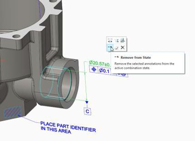
Mini Toolbars for 3D Annotations
Mini Toolbars are introduced for 2D and 3D Annotations.
User Interface Location: Click the Annotate tab
Semantic Query in Model-Based Definition
You can query models per ASME and ISO standards and analyze semantic information related to annotations.
User Interface Location: Semantic Query is available in the Query group of the Annotate tab. Semantic Query is also available from the mini toolbar for annotations.

Semantic Query is a special analysis mode that helps you to obtain the semantic information related to annotations.
Click Annotation ▶ Semantic Query to open Semantic Query mode. In this mode, you can query annotations and analyze the complex relationships between the annotations and the geometry in a Model-Based Definition (MBD) environment.
Enhanced Datum Feature Symbol Attachment Option
You can attach a Datum Feature Symbol (DFS) to a GTOL that is placed on a dimension. This improves DFS placement compliance to the relating ISO 5459- 2011 and ASME Y14.41-2009 standards.

3 Sheet Metal
New Types of Corner Reliefs
New types of corner reliefs provide more geometrical solutions. User Interface Location:
- In the Shapes group click Flange ▶ Relief and then select Corner Relief.
- Click Flexible Modeling ▶ Sheet Metal Objects ▶ Edit Corner Relief.
- Click Flexible Modeling ▶ Sheet Metal Objects ▶ Recognize Corner Reliefs.

Flattened Representation of Sheet Metal Part Is Improved
Defining a flat pattern representation of a sheet metal part is improved and simplified.
User Interface Location: In the Graphics toolbar click Flat Pattern Preview.
Closed Section for Bend Relief
You have more control when creating closed sections for bend reliefs. User Interface Location:
- Click Model ▶ Flange ▶ Relief.
- Click Model ▶ Flat ▶ Relief.
- Click Model ▶ Editing ▶ Join ▶ Relief.
- Click Flexible Modeling ▶ Edit Bend Relief ▶ Shape.
There are three new options to control length:

NEW FLAT WALL FUNCTIONS
- Auto-detect neighbor walls
- Bend position made easier
- Mini toolbar support

4 Enhanced User Interface and Experience
Creo 8.0 aims to make it easier to bring your ideas to life with a more new datum display interface, including shaded planes and color coordinate systems. You can also detach and display multiple dashboard panels and control the transparency display for various items. If you use Sketcher in Creo 8, you’ll enjoy the new control options for dimension visibility.
Additional Commands for Showing and Hiding
There are additional commands for showing and hiding objects. User Interface Location:
- Right-click an object in the Model Tree or Graphics window and select Show All or Show All Except from the shortcut menu or the mini toolbar.
- Click View and then in the Show box select Show All or Show All Except.

Tips: Click View ▶ Reset Status to reset to the original visibility configuration.
Mini toolbar and RMB functions
- Feature mini toolbar and dimension toolbars

- Access to most important tool options from the graphics – Left-click: mini toolbar only – Right-click: mini toolbar + right mouse menu

Dimension background
- The background of the dimensions is changed
- Possible to change it under the View tab.
- Color and transparency can be changed

New dashboard layout
- Buttons with text
- Improved help

Model Tree enhancement
- Insert here is replaced by a line:
- Blue line with dot in parts
- Green line on assembly level
- Active part is more visible, other parts are greyed out
- No more tree.cfg file needed (modification stored by ui file automatically)

Automatic drawing naming
Drawing can take the same name as the part

Data management
Windchill Status in Model Tree

New Multibody Design
One of the brand-new features in PTC Creo 8 is the ability to complete multibody design. The tools allow engineers to work with complex designs that may have overlapping, touching, or disjointed geometry. These abilities are particularly useful for designing products that use new manufacturing technologies, like 3D printing.
It is also the ideal solution for designing multi-material over molds for injection molded parts and components. Multibody design is particularly helpful when working within today’s modern development processes involving the design of complex products across teams. It optimizes the design process so you can move forward quickly and with fewer errors. Your team can effectively generate designs for high-quality, cost-effective products that get to market faster.

5 Assemblies
Inseparable assemblies – easier component management of purchased parts
Using purchased components in your assembly? With an inseparable assembly, you can include it in your model and do the following:
• Embed: Copy and embed the component into its owner assembly.
• Extract: Extract the component to a new standalone model, replacing the embedded component in the assembly.
• Make Inseparable: Embeds the lower-level components into the selected assembly.
• Make Separable: Extract the embedded components from the selected assembly.
• Create embedded: creates a new embedded component in the assembly.

Piping
Removing Pipe Segments
Use the Remove Pipe Segment tool to reduce the number of pipe segments, cuts, and welds.
User Interface Location: Click Tools ▶ Remove Pipe Segment.
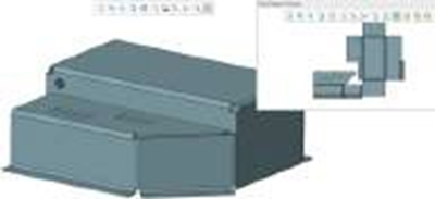
Note: When you use the Remove Pipe Segment tool, the design is reduced to 4 pipes, 10 welds, and 4 pipe cuts, as you can see in the image below. In addition, you may be able to reduce the count to 2 pipes, 9 welds, and 2 pipe cuts.
Pipeline before removing a segment

Pipe segments minimized after using
Remove Pipe Segment

For more details please check PTC.com
Comments are closed